
The GMT-Consortium Large Earth Finder (G-CLEF) will be a cross-dispersed, optical band echelle spectrograph to be delivered as the first light scientific instrument for the Giant Magellan Telescope (GMT) in the mid 2020's. G-CLEF is vacuum-enclosed and fiber-fed to enable precision radial velocity (PRV) measurements, especially for the detection and characterization of low-mass exoplanets orbiting solar-type stars. The passband of G-CLEF is very broad, extending from 3500Å to 9000Å. This passband provides good sensitivity at blue wavelengths for stellar abundance studies and deep red response so as to permit observations of high-redshift phenomena.
The design of G-CLEF incorporates several novel technical innovations and methodologies when compared with previous PRV instruments and instrumentation for ground based telescopes in general. G-CLEF has recently passed preliminary design review (PDR) and a subsequent gate review of the spectrograph optical design. More details on the design of G-CLEF can be found in Szentgyorgyi, et al., 2014.
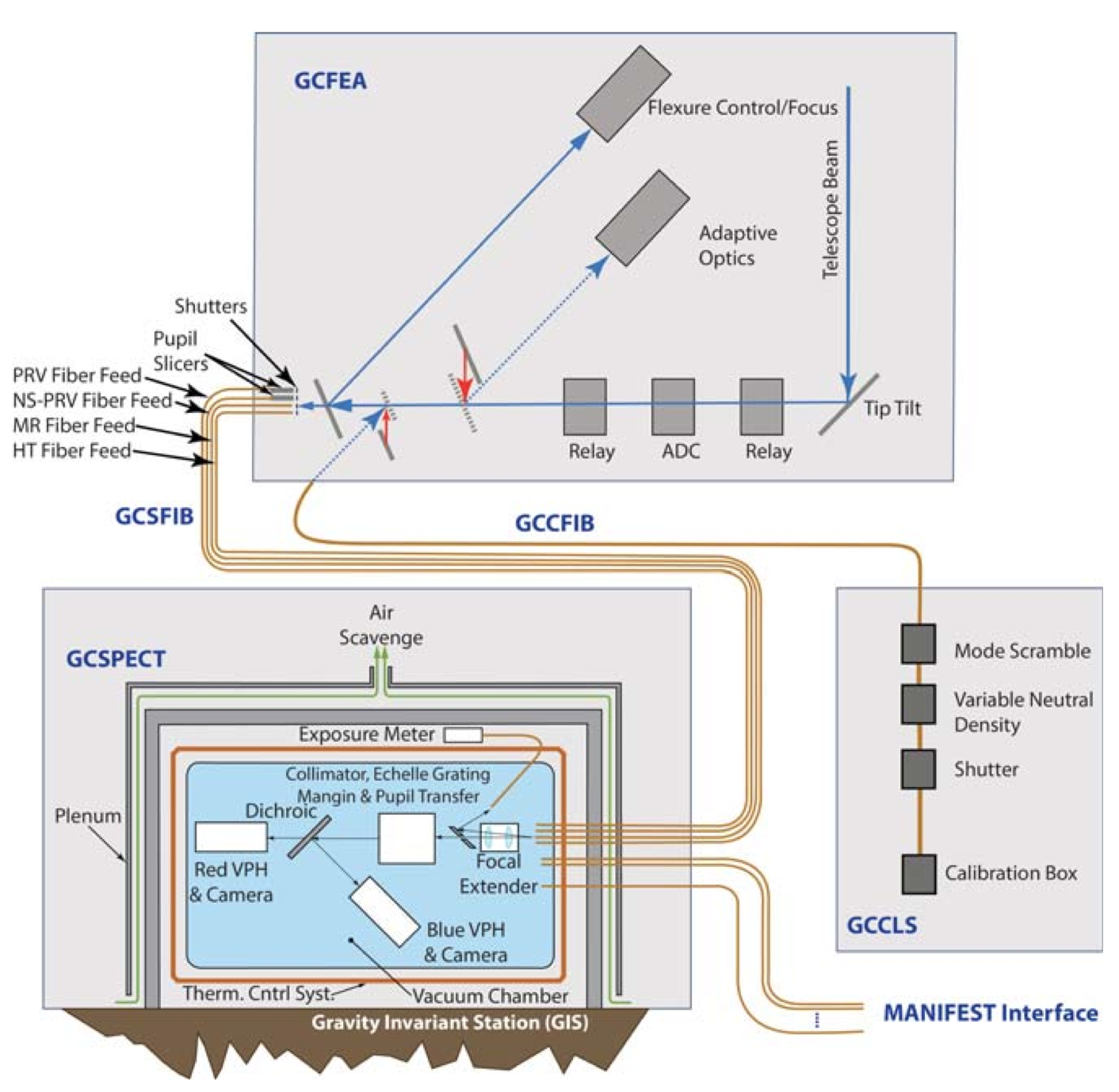
In particular, G-CLEF will be the first PRV spectrograph to have a composite optical bench to exploit that material’s extremely low coefficient of thermal expansion and high stiffness-to-mass ratio. The design also incorporates a unique thermal control system design that maximizes instrumental immunity to ambient temperature fluctuations. This system has been prototyped and has demonstrated sub-millikelvin thermal stability on diurnal time scales.
The spectrograph camera subsystem is divided into a red and a blue channel, split by a dichroic beamsplitter, so there are two independent refractive spectrograph camera designs. These designs minimize lens fabrication risk while maximizing performance as measured by point spread function size, throughput and immunity from ghosting and scattered light. The exposure meter has been implemented as a subsystem of the camera and harvests out-of-order light at the volume phase holographic gratings, which cross-disperse the two spectrograph beams after the dichroic.

The control system software is being developed in model-driven software context that has been adopted globally at the GMT for all telescope systems.
 |
 |
G-CLEF has been conceived and designed within a strict systems engineering framework. As a part of this process, we have developed a powerful tool set to assess the predicted performance of G-CLEF as it has evolved through subsequent design phases.
Instrument Characteristics
| G-CLEF Property | Value |
|---|---|
| Spectrograph Beam Diameter | 300 mm |
| Echelle Grating Facet Count | 3 |
| Spectrograph Focal Ratio | F/8 |
| Collimator focal length | 2400 mm |
| Fiber Output Focal Ratio | F/3 |
| Pupil Xfer focal lengt | 1600 mm |
| Camera Beam Diameter | 200 mm |
| Pup.Xfer Mirr./Cam. Reduction | 450/1600 = 0.2813 |
| Camera Focal Ratio | F/2.25 |
| PRV Slit Image Size | 0.075 mm |
| Camera Focal Length | 450 mm |
| Baseline Pixel Size | 0.010 mm |
| Passband | 3500Å-5400Å (blue) & 5400Å-9000Å (red) |
| Camera lens count (blue/red> | 8/7 |